How To: Use your custom floorplans as 2D Plans
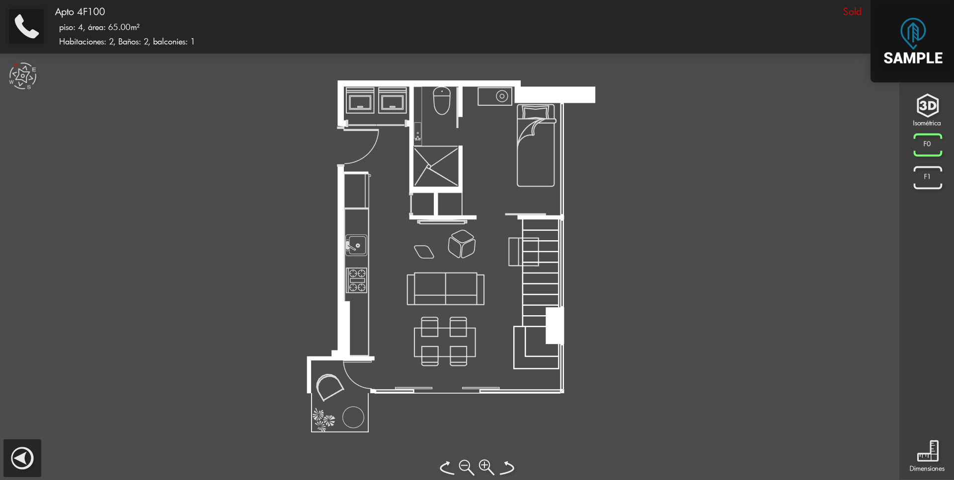
There are many ways to show your 2D plans on the app, this is the first screen that shows when you enter an unit
If you used the Wall Generation Script, this whole 2D floorplan is generated and all the elements are placed correctly in 3ds Max and the hauzdEditor will detect it automatically, so you don´t really need to make something else.
But sometimes, your client may require a custom 2d screen or they want their own imagery on the 2d plan, we may receive 2 types of source materials from our client:
Rasterized Images (.jpg , .png, .psd)
Vectorized/ CAD drawing (.ai, .eps .dwg)
Rasterized Images (.jpg , .png, .psd)
Vectorized/ CAD drawing (.ai, .eps .dwg)

ONE OF THE MOST IMPORTANT THING IS THAT YOU MAKE SURE YOU RECEIVE THE BEST FILE AVAILABLE, WITH MOST EDITABLE CAPABILITIES AND BETTER RESOLUTION
RASTERIZED SOURCE
For this tutorial, we will use an editable .PSD, you can edit layers and select everything we want or we don´t want.
First thing we´re going to do is set the image size to 2048x2048 (Power of Two dimension) and we´re going to remove the white background and use alpha, this way, we can use it as a texture, inside 3ds Max.
Exported Image:
The next thing to do is to go to your 3ds Max Scene, create a square plane and create a material with this texture, and of course, assign that texture to our plane
Note that it uses the common plan_ Prefix so the engine can detect it as a 2d Element, and its nothing special in terms of material, only the diffuse and opacity input are being used, once exported the scene with the 3ds Max Script, and importing it to the engine, it will work perfectly fine on the 2d screen

Rasterized Method Pros:
• Really quick and easy
• It gives more Color to the 2d Screen that the default generated using wall Generation Script
• You can add much more information in the image
Rasterized Method Contras:
• Needs to use the highest resolution possible to avoid pixelation, and even using the max 2048x2048, it still gets pixelated using max zoom
VECTOR/CAD SOURCE
For this tutorial, we will use a .PDF, this is one of the most used format by our clients, in the best case scenario, this .pdf is created using a good source file, so we can export it again to a .dwg, .eps or .ai.
How we can know this file may work?
How we can know this file may work?
Opening the file with adobe illustrator, and using the shortcut CTRL+Y we can check the splines used in the .pdf, if you can see correct splines that matches the normal view, then you can use this file
This is a good example, you can see there are visible splines on the file, these are mostly shapes that we can use to create the 2D elements
This is a bad example, you can see there is not many editable elements when inspecting the file with Ctrl+Y, the simple rectangle element means that its a merged rasterized image, and the rectangular elements with diagonal cross lines means that its also a rasterized file but merged using an external reference
This type of source file WONT work as a Vector/CAD material, but since it contains rasterized information, you can use the previous method (RASTERIZED) to import this file as a 2d element.
Keeping this in mind, lets work with the first type of pdf:
First thing we should do in adobe illustrator is to EXPAND the vectors (this will remove all splines and strokes and convert them to a SOLID FILLED geometry)
First thing we should do in adobe illustrator is to EXPAND the vectors (this will remove all splines and strokes and convert them to a SOLID FILLED geometry)
Select your desired Geometry, on the top menu bar go to Object→Expand→Select Object,Fill and Stroke
Why we need to expand?
This vector file can contain all types of information, splines, texts... so we need to make sure all the spline based information (mostly, lines and texts) are bidimensional so we can convert it to a proper object in the next steps. Please note that once the texts are expanded, you won´t be able to edit it as text (typing), you will convert the text to curves.
After you have expanded all the splines, you will merge your desired elements using the PATHFINDER, this will MERGE all vector elements into just one, this will remove all intersecting paths and make a cleaner version of all the drawing; it works kind of like a boolean in 3d Elements.
You can activate the pathfinder options by going to the top bar menu, Window→ Pathfinder
Now, we need to select all the desired elements to merge, and click on the MERGE option of the pathfinder
IF IT LOOKS LIKE ITS NOT WORKING AT THE FIRST TRY, REMEMBER TO UNGROUP(Object→Ungroup) AND RELEASE ALL CLIPPING MASKS (Object→Clipping Mask→Release)
We will now end with a single element and we can use these lines to create the geometric element
We can clean up some other elements and vector and EXPORT IT AS DWG OR .AI (SET ILLUSTRATOR 8 IN THE COMPATIBILITY EXPORT POP UP)
The rest of the process will be really simple , import the file to your 3ds Max Scene, convert it to Editable Mesh, assign it a solid color material, use the plan_ prefix
I CAN'T STRESS THIS ENOUGH, DON'T FORGET TO SET YOUR UNITS AS GENERIC UNITS AND SYSTEM UNITS SET TO METERS, OTHERWISE, YOU WILL PROBABLY GET WEIRD RESULTS IN 3DS MAX
Even if it is, max uses its own algorithm so there´s still a probability that the vector, even if its correct, does not produce the desired geometric mesh, try to clean the vector as much as you can, avoid very small elements, and do all the "problem solving" as you can.
Incorrectly Generated Mesh:
Correctly Generated Mesh
After importing the elements, you will be able to see the geometric 2d elements based on the vector source

Vector/CAD Method Pros:
• it uses geometric meshes so it wont be pixelated, no matter the zoom, the graphic will always be sharp
• Looks cleaner and gives the 3d screen the whole spotlight

Vector/CAD Method Contras:
• You will probably need much more time to do all this process and clean the vector data or geometry
Related Articles
Everything About Plan 2D
In HauzdEd To activate or deactivate the 2d option of the scene, go to your scene blueprint and check "Import 2D" Having this option enabled, you will have the option to import and view the 2D Elements The engine will import and use the element ...How to: Create and use Forms for Reservation, Quote and Lead generation
Creating a hauzd project means you will have a powerful 3D application tool to sell your Real Estate Project. We have recently launched a new feature that allows your Sales Team to catch the information of the users, send quotes automatically and ...Choose the Plan that fits your needs | Subscription fees
• New hauzd subscription fees starting from Aug, 20th, 2020. • How to choose a plan according to your needs. • Upgrades to 3D Assets • Subscription Time This pricing is only valid for new projects created in our platform, starting on Thursday, Aug ...hauzd 2.0 Introducción - Floorplan Generation
hauzd 2.0 Prefixes
This article will be divided in 2 parts: -Prefixes needed for 3D Modeled objects. -Prefixes needed for Wall Generation 2.0. What are prefixes? A Name prefix is a keyword that goes infront of your object's name, right at the very beggining, and for ...